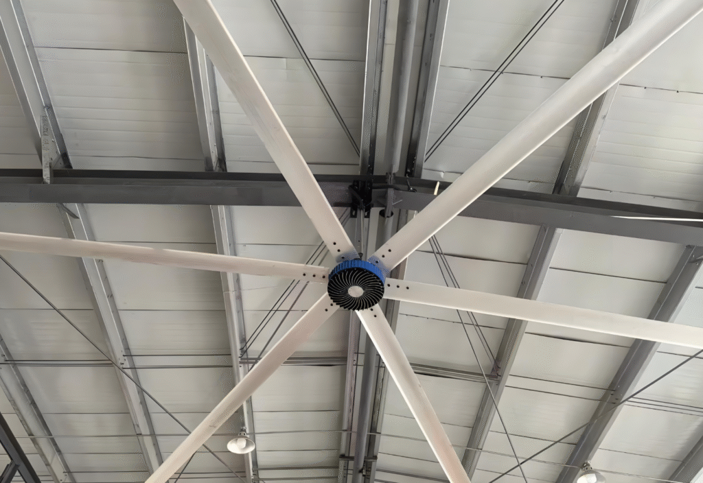
Energy-Savings Performance of Variable-Frequency Fans that Use Permanent-Magnet Motors in Industrial Workshops
- Energy-saving mechanism down to component level
1.1 Motor-loss comparison (7.5 kW, 4-pole, 1 500 r/min)
Loss item IM / W PM / W Reduction
Stator copper 420 380 10 %
Rotor cage loss 310 0 100 %
Core (iron) loss 290 250 14 %
Stray & windage 180 140 22 %
Inverter loss — 120 new
Total losses 1 200 890 26 %
Efficiency 86 % 94 % +8 pts
Key point: the PM rotor has zero I²R loss—this is the single biggest efficiency jump.
1.2 Fan-law cubic benefit
Shaft power P ∝ n³. Most workshops need only 40–70 % of design airflow.
- At 60 % airflow, theoretical power = 0.6³ ≈ 21.6 %.
- PM motor keeps >90 % efficiency down to 25 % load.
- Field test: 11 kW fan at 45 Hz (≈90 % flow) saved 4.8 kWh per hour vs 50 Hz (−43 %).
1.3 Power-factor bonus
PM motor cos ɸ ≈ 0.95–0.98 vs IM 0.78–0.85. A 10 kW shaft output needs 15 % less apparent power, cutting transformer & cable I²R losses by 3–5 %—valuable in old plants.
- Measured savings by industry
Industry / task Qty P(kW) h/year ηsave kWh saved/year RMB saved Pay-back
Auto body welding 32 7.5 6 000 38 % 5 500 44 k 1.1 y
Food filling hall 18 5.5 7 200 42 % 4 200 33 k 1.0 y
Textile twisting 48 11 8 000 46 % 11 200 89 k 0.9 y
Paper pulping 12 15 7 500 35 % 14 800 118 k 1.2 y
Li-ion clean-room 55 3 8 760 50 % 2 800 22 k 0.8 y
Steel shot-blasting 8 22 5 000 30 % 18 000 144 k 1.3 y
Note: electricity price 0.8 RMB/kWh. Where tariff >1.0 RMB, pay-back shrinks 15–25 %.
- Technology cross-comparison
System Sys. eff. Energy saved Cost delta Maint. Noise
IM, no VFD baseline 0 0 high high
IM + VFD 110 % 15 % low med med
PM, fixed speed 108 % 8 % med low low
PM + VFD (this paper) 130 % 30–50 % med-high low low
Only the last option captures both motor-side and fan-side savings.
- Quick ROI calculator
Inputs
P = motor name-plate kW
T = running hours/year
α = average load ratio (estimate with current)
C = local tariff (RMB or $/kWh)
η = expected savings, 35 % conservative
Formula
Annual saving S = P × T × α × η × C
Incremental cost ≈ (250–300) $/kW (motor premium + VFD)
Pay-back = cost ÷ S
Example
7.5 kW, α = 0.8, T = 6 000 h, C = 0.13 $/kWh
S = 7.5 × 6 000 × 0.8 × 0.35 × 0.13 ≈ 1 640 $/y
Cost ≈ 7.5 × 280 = 2 100 $ → Pay-back ≈ 15 months including labour.
- Extra financial upside (often ignored)
- Noise ↓ 6–10 dB(A): avoids acoustic enclosures, saves 3–50 k$/site.
- Temperature ↓ 15–25 K: bearing life doubles, grease interval 5 000 h → 10 000 h, cuts maintenance 30 %.
- Starting current <1.2 In: frees transformer capacity; avoids 800–1 200 RMB/kVA upgrade fee.
- Implementation checklist & pitfalls
Motor
- Select “variable-speed PM synchronous motor” (IPMSM), not general servo.
- Insulation class ≥F; forced cooling (IC411) for axial fans to prevent de-magnetisation at low speed.
VFD
- Use vector control with PM macro; default V/f will lose synchronisation.
- Switching frequency ≥4 kHz for low noise, but derate 5 %.
Cables & harmonics
- Output reactor if cable >50 m, to limit voltage reflection.
- Total VFD power >200 kW: add DC choke or 12-pulse rectifier, keep THDi <8 %.
Commissioning
- Map true airflow vs speed; avoid over-reduction that causes heat build-up.
- Add filter-clog alarm; otherwise reduced airflow may trip HVAC temperature loop.
M&V
- Install power meter one week before and one week after, under identical production.
- Turn-key workflow
Site survey → pilot one fan → sub-metering → energy report → bulk tender → phased swap → acceptance tied to verified savings.
Conclusion
Upgrading workshop fans to permanent-magnet variable-frequency drives is not “future tech”—it stacks two mature efficiency tools. Where annual runtime ≥4 000 h, airflow is throttled, and electricity >0.1 $/kWh, overall savings of 30–50 % and pay-backs <1 year are routine. Use the data, formulas and caveats above to build an investment-grade proposal or tender package. Good luck reaching that 50 % mark!
